

Building a Bookstore Service Robot with ROS 2
Table of Content
Challenge 1: Building an Approachable ROS 2 Architecture for the Team
Challenge 2: Designing a Central Task Server for Multiple Service Scenarios
Challenge 3: Integrating Multiple Modules into One Working Robot System
Project Timeline: July 2025 ~ August 2025
Introduction
Project Context
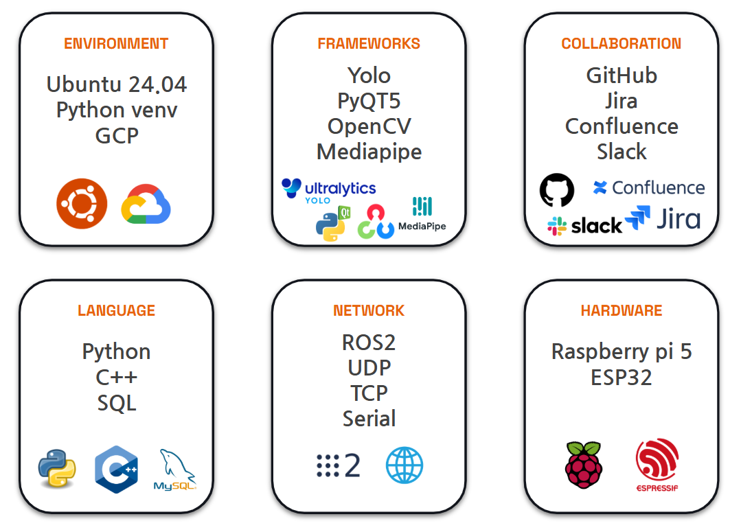
Tools and technologies used during this project
This was a four-week team project where five developers built a ROS 2-based self-driving service robot prototype for a bookstore environment.
The base robot platform, including the wheels, motors, Raspberry Pi, and low-level motor control modules, was provided by the bootcamp academy.
Our team focused on building the higher-level service robot system on top of that platform, including navigation, task management, GUI control, robot status monitoring, hardware I/O, and service task logic.
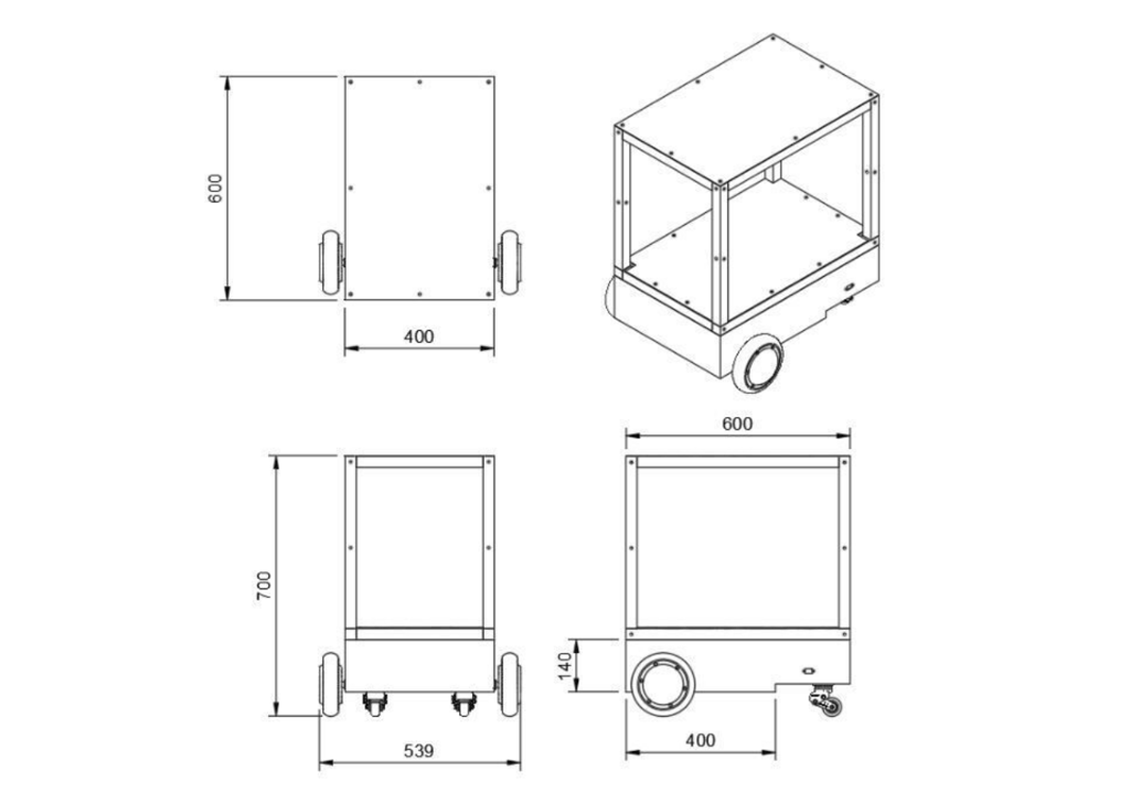
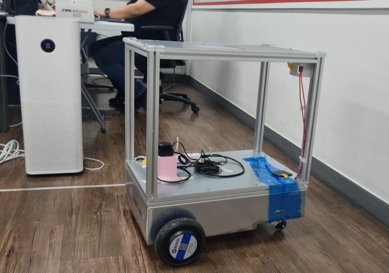
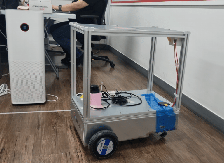
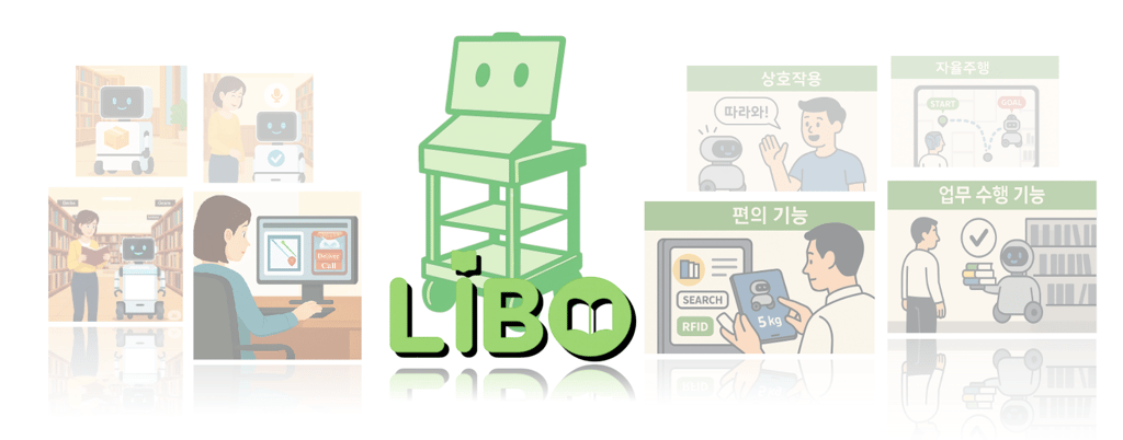
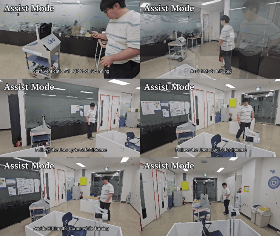
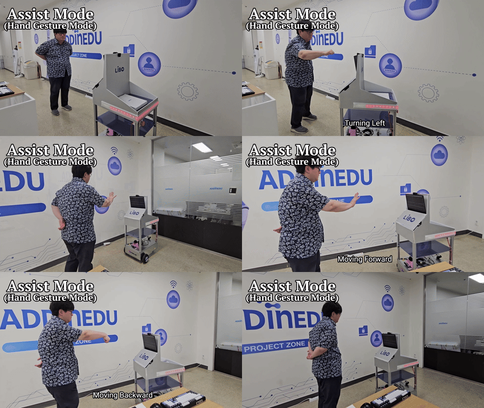
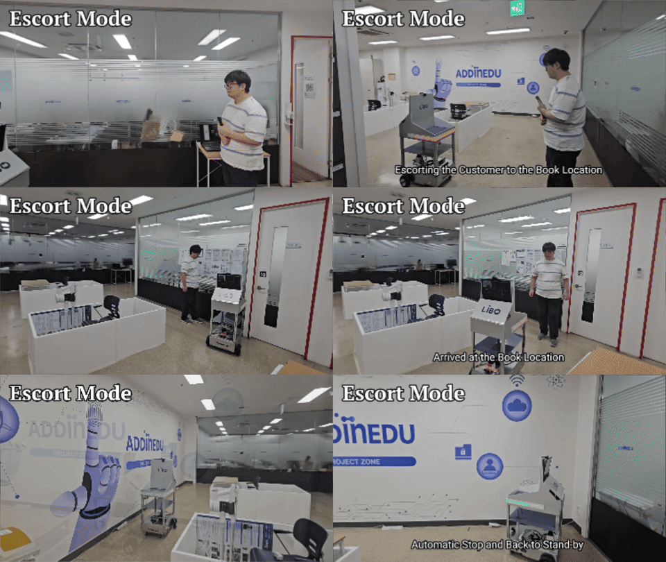
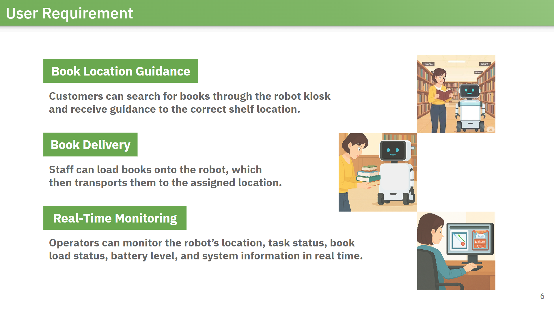
The robot was designed to guide customers to book locations, support staff with book delivery and following tasks, and provide operators with a dashboard for monitoring robot status and managing tasks.
Project Goal
My Role
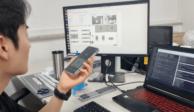
Acting as the central communication hub, I monitored the overall system and coordinated with developers responsible for other modules.
My main responsibility was designing and implementing the central server and task-management structure that integrated navigation, GUI control, robot status, hardware I/O, and service-task logic into a single, coordinated system.
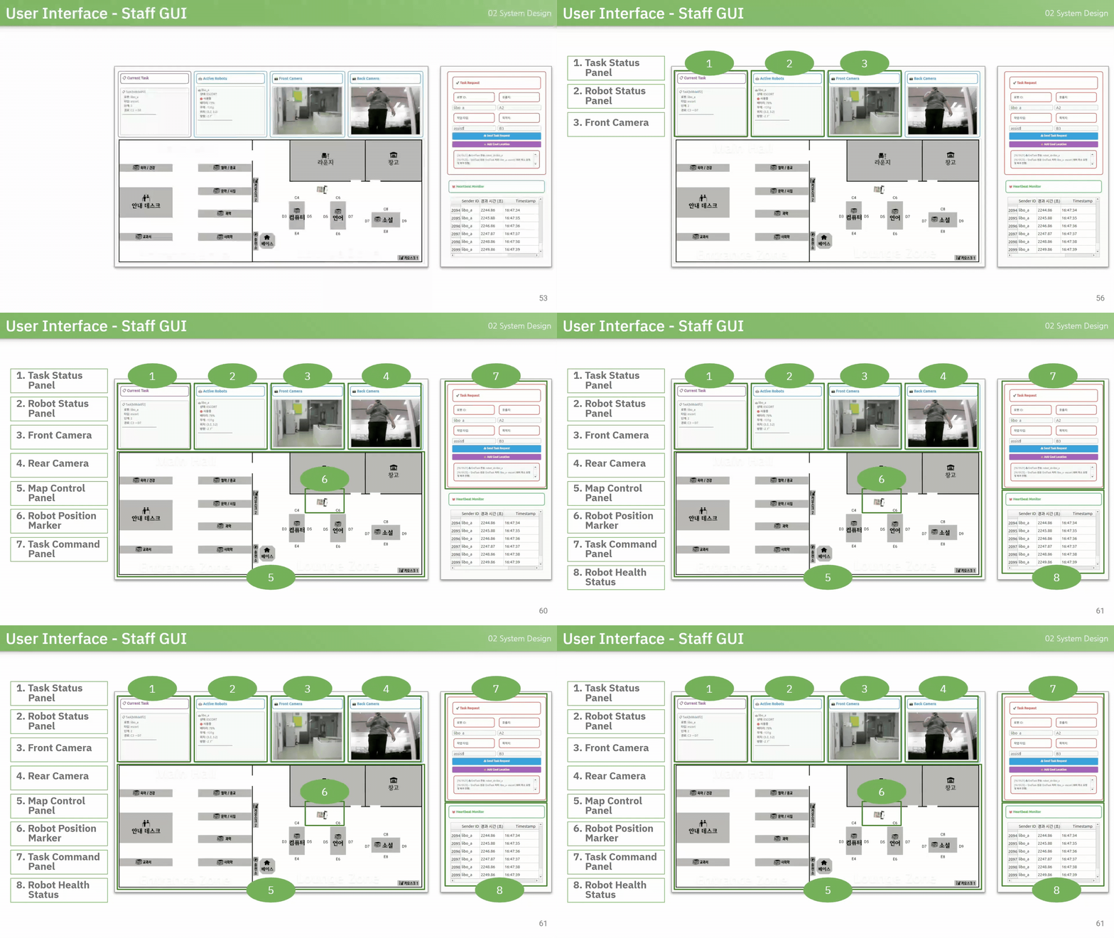
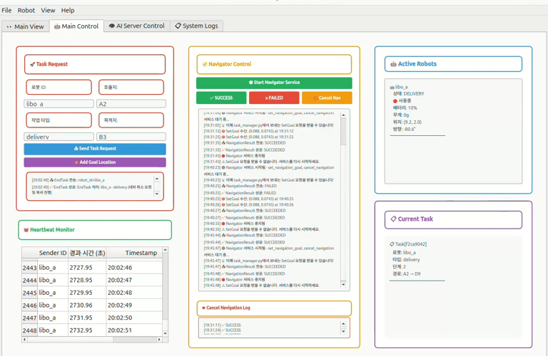
Main monitoring tab of the operator GUI I created for tracking robot status and system activity.
Challenge 1: Building an Approachable ROS 2 Architecture for the Team
The Challenge: Making ROS 2 Usable Within a Short Timeline
The first challenge was not just learning ROS 2, but making the system structure understandable enough for the team to build on.
Most team members were new to ROS 2, and the project timeline was short. If the architecture became too complex or unclear, each module could still be developed separately, but integration would become difficult later.

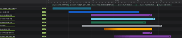
Overall project schedule organized in Jira for the month-long LIBO project.
Learning ROS 2 Through Developing the Actual Robot System
To define the architecture, I first had to understand how ROS 2 communication should fit our robot system. I studied the core communication model, including nodes, topics, services, actions, and message types, while applying those concepts directly to our service robot functions.
This helped me decide where ROS 2 should serve as the primary communication framework and where a different method was more suitable.
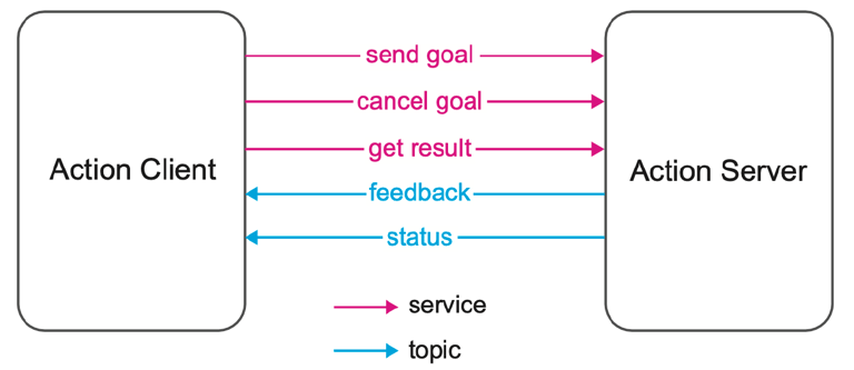
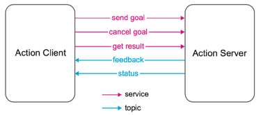
I had to understand the basic mechanisms and concepts of ROS 2 and apply them during development.
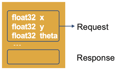
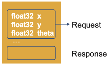

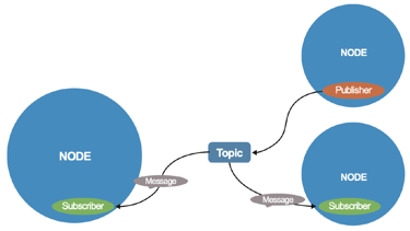
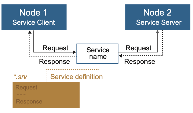
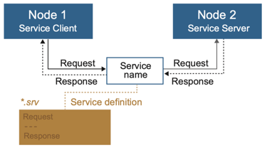
Choosing Communication Methods Based on Data Requirements
The central robot behaviour and task flow were organized around ROS 2, but not every data path fit cleanly into the same communication method. I separated the communication structure based on the type of data being handled:
Camera and vision data were handled via UDP because they were heavier and needed fast transfer.
Database communication used TCP because book data, task records, and status updates needed a more reliable delivery.
Hardware I/O was connected via serial communication to physical devices, such as weight-sensing and LED status signals.
This kept ROS 2 as the main structure for robot behaviour while allowing heavier, reliability-sensitive, or hardware-specific data paths to use more suitable communication methods.
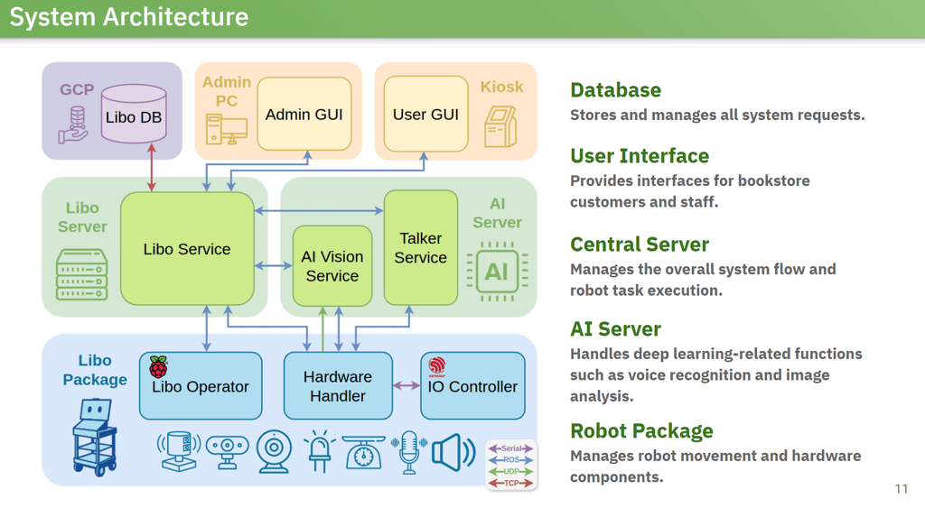
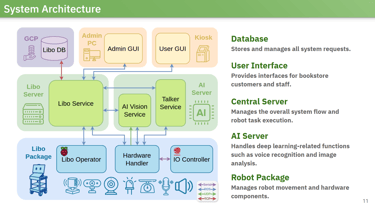
System architecture of LIBO, where different networking models were used for different tasks.
Challenge 2: Designing a Central Task Server for Multiple Service Scenarios
The Challenge: Keeping Multiple Service Flows Manageable
The second challenge was designing a central server capable of handling multiple robot service scenarios with a single, consistent structure. The robot needed to handle:
Customer escort
Staff following
Book delivery
Autonomous navigation
Availability checks
Emergency states
Without a single shared task structure, each service could quickly become separate logic that was difficult to read, test, or expand.
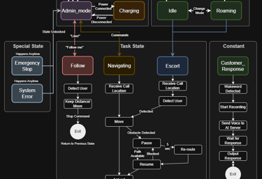
Initial flowchart showing the program flow of the robot and kiosk system.
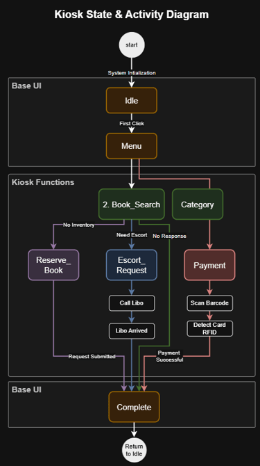
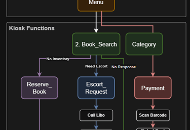
Turning Service Scenarios into Program Logic
Before implementing the server, I defined each service as a step-by-step scenario. Each scenario described:
What state should the robot enter
What action should it perform
What signal should it wait for
When should it move to the next step
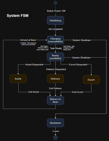
This made the task logic easier to follow because the program structure matched the actual service flow. Instead of treating each service as unrelated code, I kept them under a similar pattern so that new service types could be added with less restructuring.
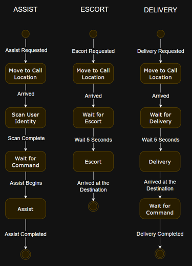
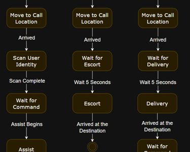
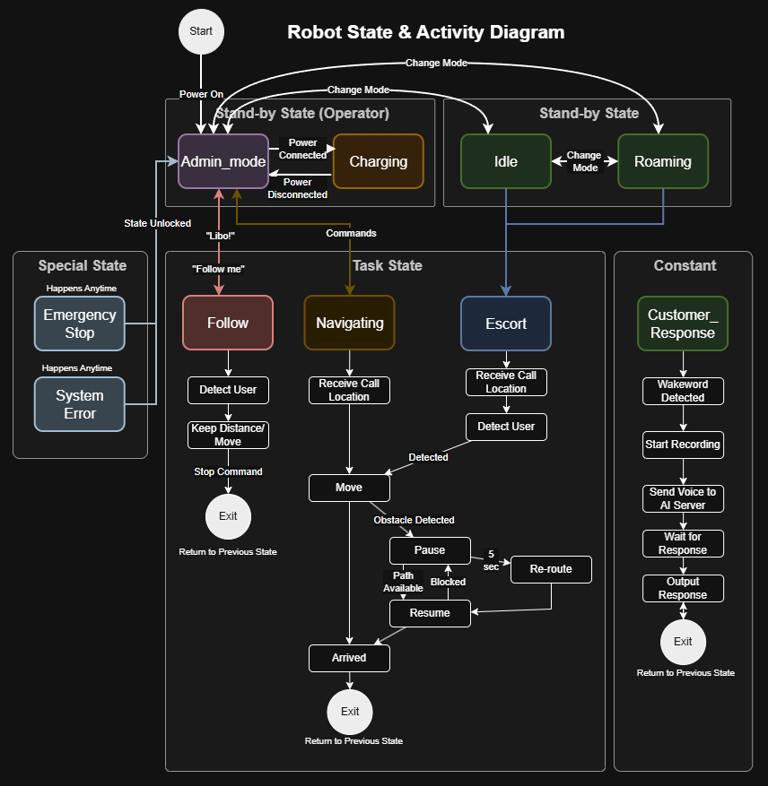
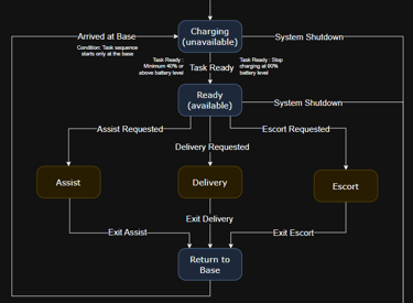
Final version of the system FSM on the left and the flowchart for the three main services on the right.
Structuring Tasks and Robots as Manageable Objects
For implementation, I structured the server around task and robot objects. Each task could be:
Created
Tracked
Assigned to an available robot
Held when no robot was available
Each service contained a sequence of actions, and the server moved through those actions while coordinating timing between modules.
Although the structure was still limited by my experience at the time, I kept each action and service function organized within the main server so the task flow stayed readable and easier to follow.
As a result, the server became the coordination layer for task creation, assignment, execution, and status tracking across multiple service scenarios.
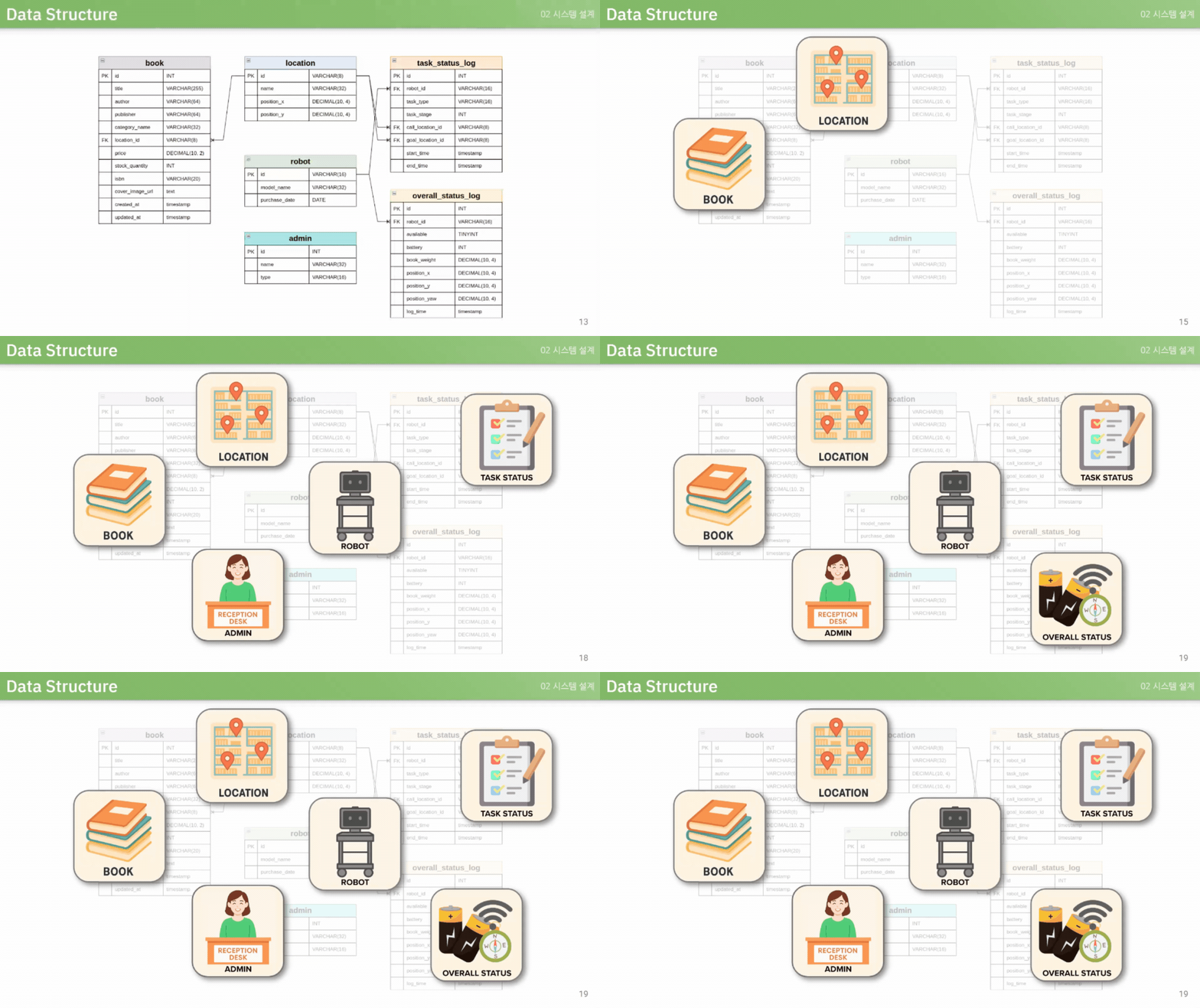
ER diagram simplified into six major entities. The central server was designed to manage multiple tasks and robots simultaneously.
Challenge 3: Integrating Multiple Modules into One Working Robot System
Coordinating Separate Developer-Owned Modules
The last challenge was integrating multiple modules developed by different team members into one working robot system. Each developer was responsible for a separate part of the system:
AI server
Hardware server
Robot Control
GUI
Data server
Since these modules had to communicate through different interfaces and data flows, integration became one of the most difficult parts of the project.
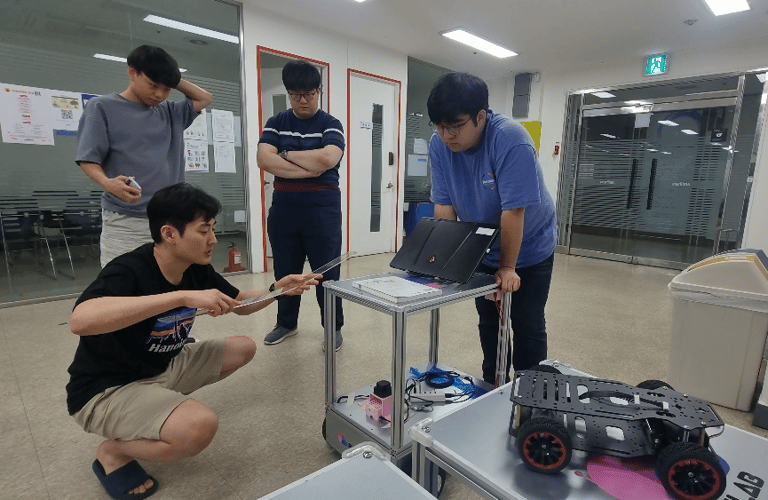
The team discussing hardware implementation on the robot. Clear communication was key to maintaining team alignment.
Defining Module Responsibilities and Data Flow
Before integration testing, I helped define each module’s responsibilities and the flow of data between them. Since I was responsible for the central architecture, I facilitated discussions around:
Module boundaries
Communication structure
The role of the main server
This helped the team work from a shared blueprint rather than connecting modules based on unclear assumptions.
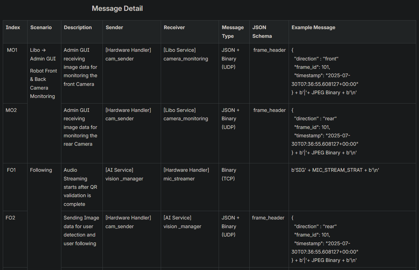
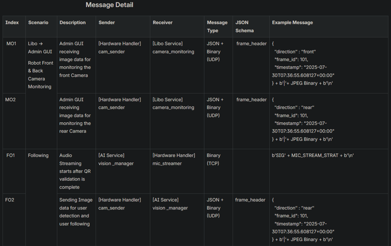
A partial example of the interface specification used to define the communication structure and reduce miscommunication between modules.
Using System Scenarios as the Integration Blueprint
A major part of integration was creating clear system scenarios with specific data flow.
These scenarios helped each developer understand how their module fits into the full service flow.
I learned that unclear scenarios often created integration problems, while precise scenarios made it easier to:
identify and troubleshoot bugs,
define expected behaviour, and
develop modules in parallel.
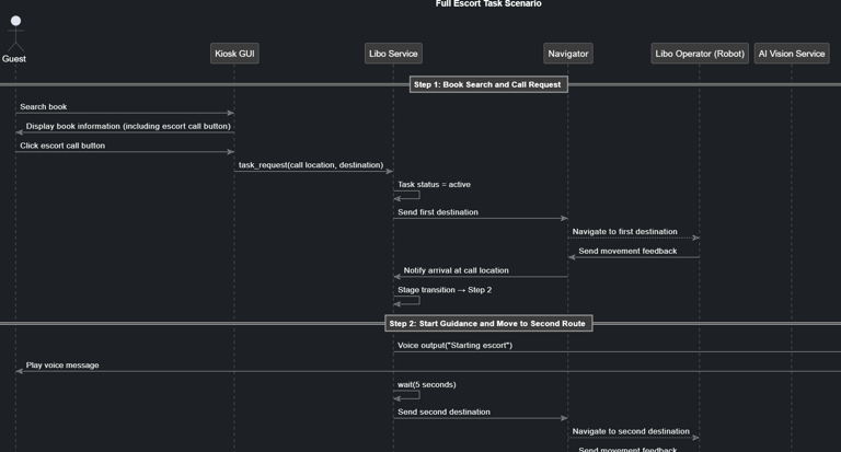
Partial sequence diagram created to design the detailed system flow. We wrote roughly 100 pages of these scenarios to define service behavior and module interaction.
Testing Early and Regularly
To reduce integration risk, I encouraged the team to test modules together as early and as often as possible. We performed:
Smaller module-to-module tests
Regular full-system integration tests
Checklist-based verification of expected behaviour
When a test failed, we broke the issue down step by step to pinpoint the exact failure point rather than treating the whole system as a single, unclear problem.
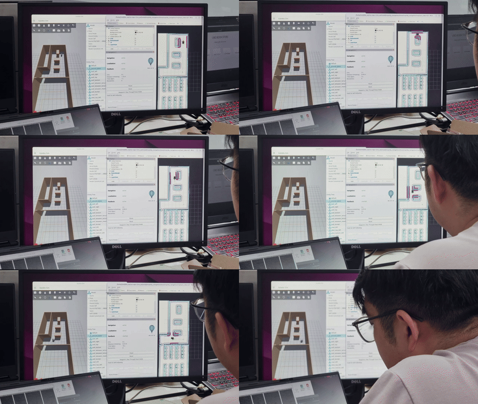
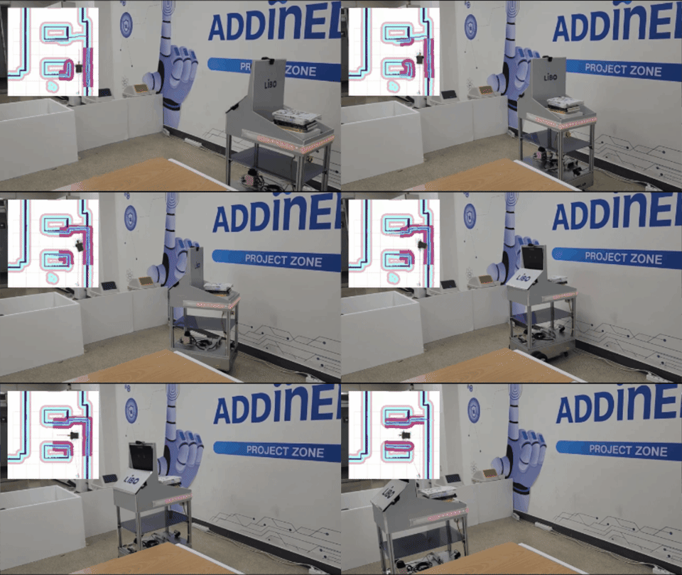
SLAM and navigation were first simulated in Gazebo and monitored in RViz before being tested on the physical robot.
Building Debugging into the Development Process
I also encouraged the team to build debugging tools and verification methods as part of each module’s development. This made it easier for each developer to test their own module and helped the team isolate the actual cause when errors appeared during integration testing.
Some of these debugging tools later evolved into practical operator GUI features.
Through repeated integration testing and clearly defined module interfaces, the team succeeded in connecting independently developed modules into a working robot system.
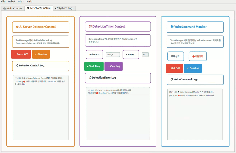
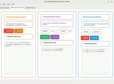
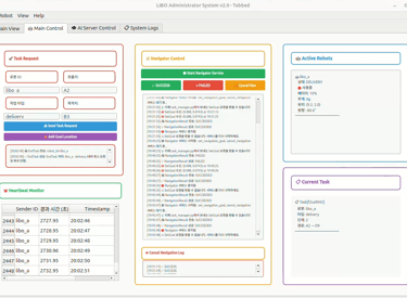
Debugging tool developed for the central server, with key features later integrated into the operator GUI.
Conclusion
Outcome
By the end of the project, our team had developed a functional ROS 2-based service robot prototype that could execute complete bookstore service scenarios.
Despite the limited timeline and system complexity, we validated the core concepts of autonomous navigation, task-driven robot behaviour, and multi-module coordination through a working end-to-end implementation.
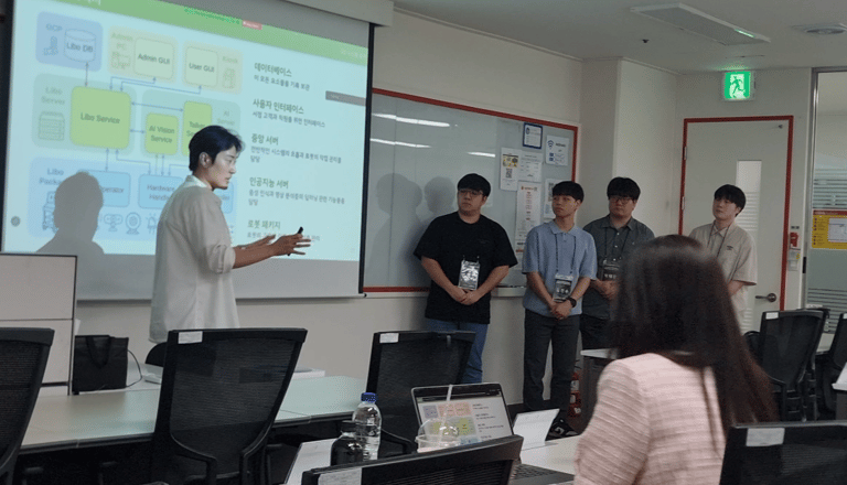
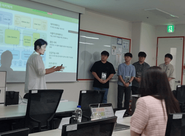
Presenting the completed project to a panel of robotics company executives in South Korea
Key Lesson: System Scenarios & Integration Testing
One of the most valuable lessons I learned was the importance of defining system scenarios before implementation. Clear scenarios helped establish module responsibilities, data flow, and expected behaviour, making both development and debugging more efficient.
I also learned that frequent integration testing is essential in robotics projects. The biggest challenges often appeared at the boundaries between independently developed modules, rather than within the individual modules themselves.
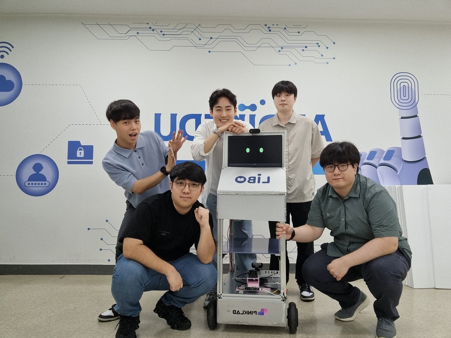
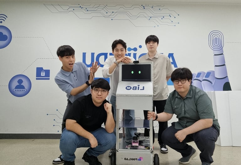
The team with the completed LIBO robot after the final project demonstration